Showing posts with label installing. Show all posts

Friday, September 2, 2011

Gravity Flow Water Systems

Welcome! This website is the culmination of my time designing and building aqueducts in the Peace Corps. I worked in rural Panama. The designs and construction were gravity-fed systems and had no pumps.

This website is meant to be general reference. There are certainly better ways of doing things and your feedback is appreciated. In addition, there may be a design or construction method that is better suited to your area.


The site is divided into three sections: design, construction, and maintenance. There are also other resources out there that I've started to link from the resources section.

A good starting place on gravity-flow water systems is to read this overview.

Monday, August 22, 2011

Installing Principle Valve Boxes

Construction
1_htm_m74d6e432

  1. Fill area below the valve box and inside the valve box with gravel. This will help with drainage and future maintenance of the valve.
1_htm_m675fab97

  1. Place the lid on the valve box and backfill the work area. The area should be backfilled with dirt only. Rocks should be removed.
1_htm_1a9a997a
  1. This is the finished valve box. The lid is bolted to the box to deter vandalism.

Building Domestic Valve Boxes

Time Required
1-3 hours

Materials List
Qty Item Notes
1 1/2” valve Type shown in photos below
1 Hole saw
1 File
1 Can of PVC glue
1 hacksaw
1 2' length of 1/2” PVC
1 3' length of 3” PVC
1 Tin can (Large) Form for concrete box cover that sits on valve
1 Sack of cement Will only use small portion (less than 1/8 bag), For concrete box cover
1 Tin can of sand For box cover
1 Tin can of rock Small aggregate, pea-size preferable, For box cover

Construction – Valve Box
1_htm_2dc3dde0

  1. Using the hole saw, drill hole on one side of the 3” tube. Repeat 180ยบ on the other side of the tube.
1_htm_3e530443

  1. Using a flat file, bevel the edges of the valve until it can fit inside the larger tube. See picture below.
1_htm_m2cef4207
  1. Here is the valve fitting snugly in the larger tube. Align the valve with the holes that have been drilled into the sides of the tube.


Construction – Cover


<under construction>


Building Tap Stands

Time Required
Day 1:    3-4 hours to pour concrete
Day 2:    Curing
Day 3:    1 hour for removing form and adding tubes

Materials List
Qty Item Notes
1 sack of cement Will only use about 5/6 of bag
1 20’ length of 3/8” rebar Will only use about 15’. Usually comes in 20’ lengths
1 15’ length of 16ga wire For attaching tube to post. Sold by the pound
3 6’ length post For bracing post form. Can use tree branches, etc.
3 4’ x 4” wood form For forming main slab. Wood thickness not important
4 3’ x 4” wood form For forming post. Wood thickness not important
2 2’ x 4” wood form For forming main slab. Wood thickness not important
2 2’ x 6” wood form For forming indent in main slab. Wood thickness not important
1 4” x 6” wood form For forming indent in main slab. Wood thickness not important
4 5-gallon buckets of sand For concrete mix 1:2:4. Approximately 2 buckets of cement in mix
8 5-gallon buckets of gravel For concrete mix 1:2:4
2 shovels For mixing concrete
1 hacksaw For cutting rebar, PVC
1 hammer For staking form
1 20’ length of string For securing post form
1 20’ length of ½” PVC Length will vary stand to stand
1 can PVC cement
1 roll of Teflon tape For faucet seal. Will use 4” piece for each stand
2 metal trowel For concrete work
2 5-gallon bucket For measuring, storing water for concrete mix
1 wooden float For concrete work
1 faucet Plastic valves have tendency to break. Worth spending extra $ on good faucet
1 ½” threaded adaptor For metal faucet to PVC connection
1 90 degree ½” elbow
1 plastic bag

Construction

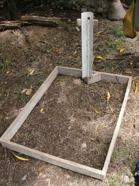
Here is a potential form for a tap stand using a PVC tube for the post. Notice the half of the 1/2" tube in the post to have an indentation in the form for the tube running up the post from the ground.


Here are photos for the construction of a tap stand.

1_htm_39799c74
  1. Determine tap stand location with community member. Explain drainage concerns and determine exact location of tap.
  2. Clear area where tap stand will be built. Make sure area is flat. A slight uniform slope away from the tap is preferred for drainage.
  3. Setup form as shown in picture. Stake along outside perimeter of form.
1_htm_6ac744dc

  1. Choose location near tap stand for mixing concrete. There will be some residual concrete after mixing that the community member may want to take advantage of.
  2. Mix concrete using 1 part cement, to two parts sand, to two parts aggregate. A good starting mixture is one bucket of cement.
NOTE: See Rebar & Concrete in construction section of website
1

  1. Once you have poured about half the pad, lay out the rebar as shown. Tie the rebar together at connection points
  2. Tie L-shaped rebar for the post to the rebar frame for the main slab.
  3. Pour remaining of main slab. Smooth trowel finish.
1_htm_m739df274

  1. Once you have poured the slab, place the form for the concrete post on the slab, enclosing the ‘L’ rebar for the post.
  2. Tie form together with string. Make sure form meets at joints so that no concrete can escape during curing process.
1_htm_35bb833b

  1. Attach poles to form for concrete post so that the post will not move during construction and curing.
1_htm_456bf5ab

  1. Pour concrete into post. Make sure to knock sides of form to release air in concrete mix.
  2. Use a stick to tamp down concrete during this process.
  3. Make sure rebar is centered in post while pouring concrete.
1_htm_47b7f742

Alternate Design: A 4” PVC tube can be used in lieu of the wood form as shown in the picture to the left.
1_htm_m5ba710da
  1. Wrap a piece of ½” PVC in a plastic bag and pass through form. The plastic bag will make it easier to remove the tube afterwards.
  2. Attach the 90 degree elbow to the tube and insert into hole of form. The tube will run flush against the post so the form needs to have negative space for the elbow to fit flush as well.
  3. Pour remaining part of the post, making sure that the rebar does not directly touch the PVC tube in the form.
  1. Cover the form and wait at least 2 days before removing form so that the concrete can cure.
  2. Make sure the concrete stays moist during this time so that the concrete can cure.
1_htm_6645d8c5
  1. Once the form has been removed, the connection can be made. Measure and cut the PVC pipe. Connect everything once before gluing to make sure everything is OK.
  2. The metal faucet should be attached to the threaded PVC adaptor. Wrap a piece of Teflon tape around the brass threads of the faucet and screw onto the adaptor. This portion will not be glued.
1_htm_2cbb6cbf

  1. Connect ½” tube to adaptor. Run tube through concrete post.
  2. Connect 90° elbow to tube. Run 1/2” tube down to ground.
  3. Add elbows and tube as needed for specific tap stand design.
1_htm_4e42e439
  1. Once connections have been glued, secure tube to concrete post by using the 16ga wire. Wrap the wire around the post once then tighten. Secure tube in three places along post.

Installing Cleanout/Shutoff Valves

Time Required
Less than 1 hour for installation

Materials List

Qty Item Notes
1 Valve Dependent on size of tube at valve location
1 Cloth rag For cleaning before gluing
1 Can of PVC glue

Construction
Installing the valves are pretty straightforward.  Cut into the tubes and install as needed.  This picture can be used as a guide.  This setup allows for the system to be shutoff and the cleanout opened so that the entire flow is redirected out the cleanout valve.  Cleanout valves can also be installed without a corresponding shutoff valve.

1_htm_m6e89adab