Showing posts with label designs. Show all posts

Friday, September 2, 2011

Gravity Flow Water Systems

Welcome! This website is the culmination of my time designing and building aqueducts in the Peace Corps. I worked in rural Panama. The designs and construction were gravity-fed systems and had no pumps.

This website is meant to be general reference. There are certainly better ways of doing things and your feedback is appreciated. In addition, there may be a design or construction method that is better suited to your area.


The site is divided into three sections: design, construction, and maintenance. There are also other resources out there that I've started to link from the resources section.

A good starting place on gravity-flow water systems is to read this overview.

Tuesday, August 23, 2011

Designing Intake Structures

Why is it Needed
The intake structure is it all begins. This is the water source for the community. You can have multiple sources feeding into the same aqueduct system. Typically, the intake structure is built into a small spring or creek, but could also represent a dam for a larger stream or river. Since this is the water the community will be drinking, make sure that the watershed (200+ meters in all directions from the intake point) is free of contamination (livestock, other villages, etc.).
Design
The design varies from source to source. For a spring, look at either a dam or intake box. For a stream, a modified dam structure can be used. Design ideas are located in the gravity-flow handbook. Consult with an engineer or someone who has experience designing and building intake structures prior to construction.
Make sure that the source is free of contamination.
Conduct a census of the community.  Figure out a good growth rate multiplier to find the population at the end of the life of the aqueduct.  Usually a system is designed for thirty years.  What is the expected population thirty years from now?  Use WHO’s 30 gallons/day/person, which is generous, to calculate the total water usage of the future community. 
Measure the flow of the intake structure during the dry season to find the minimum daily amount of water coming from that source.  If the flow does not produce enough to meet the future demand of the community, another source will be needed in addition or in place of the original source.

Designing Storage Tanks

Why is it Needed
Some communities do not need storage tanks because the flow from the source is sufficient all year long. The storage tank is used for temporary water storage. In many cases, community members think that storage tanks are for the drier season. It is important to show that storage will only last for a day or two and that a much larger tank would be needed to store months worth of water. In many cases, the tank serves to buffer daily water usage. The tank fills during the night when water usage is low and empties during the day.

Design
The tank site should be a flat area free of debris.  If the tank is located on a hillside, create drainage trenches around the future tank area to avoid future erosion from rain runoff.

Each tank is designed on a site-by-site basis.  An engineer should be consulted for approval of the final design.
To size a tank, you will need to create a daily water usage chart of the community. Look at daily water usage by conducting surveys in a few representative homes.  What are the daily activities and how would that affect water usage (cooking, washing, etc.)?  Create a chart that shows approximate water usage based on the hour of the day.  Look at what peak water usage will be.

Use WHO’s 30 gallon/day/person (generous) to calculate total water usage across the community.  Conduct a census of the community to look at total population.  Consider using a multiplier to base the design on a future population.

Measure the flow during the dry season of your water source.  Calculate gallons/day.  Create spreadsheet that shows daily demand for community minus the input from your source.  For peak demand, there will need to be X number of gallons to meet future community needs.  This should be the approximate size of the tank.  Double-check to make sure tank will fill at night to meet those needs during dry season.

A more detailed description of tank sizing and potential designs is located in the fabulous book, A Handbook of Gravity Flow Water Systems, Thomas D. Jordan Jr.

Monday, August 22, 2011

Designing Bridge Crossings

Why is it Needed
Most aqueducts have streams to cross or small ravines to avoid. At some point, there may be a good reason to elevate the tubes. All the bridge designs covered in this website are a variation on the same theme – tubes are attached to a suspended, taught cable that is anchored to something. In places where you can anchor to existing boulders or trees, this is preferable to creating posts and anchors because it means less concrete, which can sometimes present logistical issues in remote sites.

IMG_9961
Design
The construction section focuses mostly on bridge crossings using trees and making anchored posts.  If you have access to a hammer drill and there is an existing rock that can be used, this is an easy option.  However, this is usually a rare occurrence.

1_htm_m6935933c

Design resources are hard to find for this type of application. If you are a Peace Corps volunteer, consult your APCD as he/she may have some available software (excel spreadsheet) or reference documentation.

In general, these crossings do not experience high loads (no one is walking on them), so the important part is that the posts/anchors are properly sized given the type of soil.  For a softer soil prone to flooding, the post should be embedded in concrete at least three feet and the anchor should have a volume of about 1.5 ft3.  For rockier, more stable soil, the post and anchor can be downsized.  Review the final design with an engineer if available.

If you are using rocks or large trees as anchors, the cable alone should be sufficient for bridge crossings up to 60 feet.

The handbook for gravity flow discusses bridge crossings and shows a few design examples.  Though I haven't used them, Agua Para La Vida has a few resources on designing bridge crossings including a user guide and spreadsheet (Spanish).

Designing Principle Valve Boxes

Why is it Needed
The principle valve boxes will be located throughout the community and serve to isolate parts of the system for maintenance purposes. If your system does not have any shutoff valves, this is a good investment in the system as it makes maintenance quicker and has less impact on the community.

If the valve is located in a high-traffic area, the valve box should be robust enough to protect against tampering from children, livestock, or vandalism. Consider having the top locked. A simple nut and bolt should be enough to deter tampering. The water committee should keep the correct crescent wrench for opening the valve box.

The valve box could be a concrete box that sits in a hole in the ground and can be accessed without digging. Besides deterring vandalism, it also helps protect from any accidental machete or livestock damage. It also helps designate where the valve is located so that no digging is necessary to find the valve.

1_htm_1a9a997a

Design
In general, the point is to protect the valve without having the valve buried.  A simple concrete slab resting over a hole in the ground could work or a box as shown above.  There are many different design options that serve the same purpose.

Designing Domestic Valve Boxes

Why is it Needed
Domestic valve boxes are to protect against accidental damage with machetes and/or livestock. More importantly, they also serve to aid in the social engineering side of aqueduct maintenance. The valve at each tap stand can be shut off when someone has left the community (to avoid kids tampering) or to enforcement monthly water payments. Collecting a nominal fee each month will allow the water committee to have sufficient funds for maintaining their system without outside aid.

The domestic valve can only be opened and closed with a special key that only the water committee has.

Design
Valve box covers can be made from a concrete mix (1:2:4 with pea-size aggregate), using a tin can (large) as a form. 

Another option is simply using 3” PVC tube with an end cap.

An Overview of Aqueducts

Admittedly, before Peace Corps I knew nothing about gravity-flow water systems.  Turns out not much has changed since Roman times, including the physics.  Replace your open-channel structures with PVC tubes and you've got the basic idea.

Panama is blessed with abundant rainfall (most of the year in the Bocas region).  The water falls into your neighborhood watershed where springs feed streams, streams to rivers, and rivers to oceans.  This water is collected and distributed to provide water to a community using gravity instead of pumps.
Here's an overview of a typical gravity-flow water system in Panama.  I'll take extreme liberties in painting a picture of how easy it is to design and build your very own water system.
Intake Structure
Normally those in the community are intimately aware of where the nearest spring is to the community.  As long as that spring has good flow all year long and isn't located close to any livestock, it may be a good potential source for your gravity-flow water system.  Build a concrete box or dam to collect water into your PVC tube.  That's your intake structure.  You'll also need to do a study of the topography to determine the size of your PVC tubes and the route from the intake to the storage tank.

Storage Tank
Most likely your source (spring or stream usually) won't be enough to provide around-the-clock access to water.  After a careful study including flow, a census of the community, and the projected growth you can determine whether or not you need a storage tank to buffer the daily swings in demand.  Most of the time you design a tank to fill at night when demand is low to provide water for the community during the day.  The tank is a big concrete structure that holds about 5,000-15,000 gallons depending on the size of the community (about 250 people average).

Distribution System
Now you need to bring that water from the tank to the community.  Again, a topographical study is in order to make sure pipes are size correctly and placed in the right locations.

Each house will have a connection to a main line, just like back at home.  There will be shutoff valves for lines to do maintenance work.  We'll stand around to shoot the $#!% and watch the one guy dig the trench just like home.  It's all the same, just without pumps and heavy machinery.  Easy as pie...
---
Yes, I'm being facetious.  Part of the challenge is doing it with your community, which had a whole life they were living before you ever showed up.  People will be away getting firewood or food from their fincas.  You want them to come along on the journey because that sense of ownership is the difference between an aqueduct that works and one that falls into disarray.  Then there's funding and the complexities of design and building something in the jungle and social engineering and... you get the idea.  Easy as pie.

Designing Tap Stands

Why is it Needed
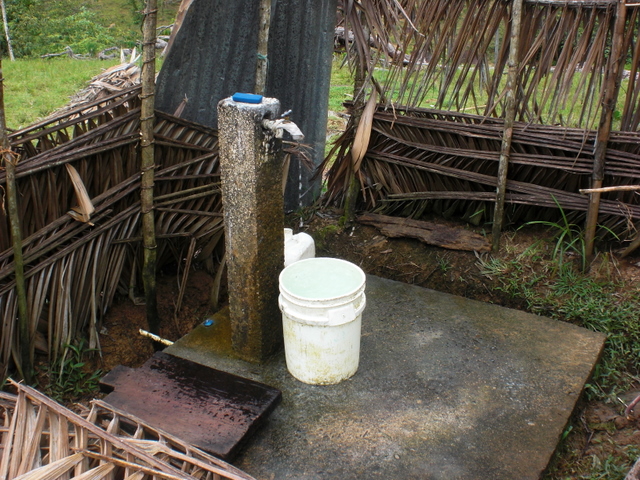
Tap stands are where community members will collect water, using the water directly for washing and bathing or filling buckets for later use. Tap stands are the component of the aqueduct that will see the most use. It is important to have a sturdy design that will withstand daily usage. Tap stands can range from a shared stand to individual stands for each house to faucets at multiple points in the home.

Design
Different tap stands are shown in the construction section.  If you have easy access to sand and gravel and are building communal stands, a more concrete-intensive design is preferable.  The design can be modified for areas where mixing concrete is more difficult. In addition, the main slab is thick and can be reduced if there is a shortage of cement, keeping in mind the tap stand needs to be sturdy enough for constant use. 

1_htm_748aad64

The tap stand consists of a 4’ x 4’ reinforced concrete slab with a 3’ reinforced post. The tube comes up from the ground, is attached to the outside of the post, and passes through the post so that the faucet is over the slab. The post can be square (wood forms) or circular (PVC form).

1

There are also photos in the construction section of taps installed directly in the home.  In this case, the PVC tube is buried up to the home and then tied/affixed to the home structural elements up to the washing area.  In this case, each home will have a different routing and design.

Sunday, August 21, 2011

Designing Cleanout/Shutoff Valves

Why is it Needed
Shutoff valves are needed for system maintenance. There should be a shutoff valve at the intake structure(s), storage tank, and at the start of the distribution system if the tank is located away from the community.
Cleanout valves should be installed throughout the system in low points in the system or along long, flat runs where sediment can build up in the pipes. Opening the cleanout valve should be part of the quarterly maintenance program in the community.

Design
1_htm_m6e89adabThe picture to the left shows a cleanout valve and shutoff valve. The system can be shutoff so that all water leaves through the cleanout valve. A Y-shaped branch would be preferred to the T shown in the picture to put less stress on the fitting.