Showing posts with label construction. Show all posts

Friday, September 2, 2011

Gravity Flow Water Systems

Welcome! This website is the culmination of my time designing and building aqueducts in the Peace Corps. I worked in rural Panama. The designs and construction were gravity-fed systems and had no pumps.

This website is meant to be general reference. There are certainly better ways of doing things and your feedback is appreciated. In addition, there may be a design or construction method that is better suited to your area.


The site is divided into three sections: design, construction, and maintenance. There are also other resources out there that I've started to link from the resources section.

A good starting place on gravity-flow water systems is to read this overview.

Working With Concrete

Concrete is a mix of cement, sand, and gravel (aggregate), and water.  A typical concrete ratio is 1:2:4. One part cement to two parts sand to four parts aggregate.


Cement
Cement is time-sensitive.  Be sure to store the cement in a dry location, protected from rain and potential flooding.  Store the cement in plastic bags, stacking vertically to get as much of the cement off the ground as possible.  The cement can pull moisture from the ground.  Older cement can still be used, but more cement is needed for the same equivalent strength.  This is outlined in the gravity flow handbook.

Sand
Avoid using beach sand when making concrete.  The shape of the grains of sand are rounder and reduce the overall strength of the concrete.  Instead, look for river sand clean of debris/silt or purchase sand from a local distributor.  Be careful storing sand as a heavy rain can wash it away.  Store on tarps or in sacks with an adequate cover.

Water
Use freshwater as saltwater can affect the curing of the concrete.  The appropriate amount of water is such that the concrete is smooth and plastic.  It should not appear runny nor so dry that it crumbles.


After mixing concrete, always cover the concrete with a plastic sheet to slow the curing process.  This will help strengthen the concrete.  Keep the concrete moist by adding water for the first 12 hours.

Tuesday, August 23, 2011

Building Intake Structures

Time Required~5 days depending on design
Materials List
Qty Item Notes
sack of cement Dependent on final design
20’ length of 3/8” rebar Dependent on final design
16ga wire For tying rebar. Dependent on design. Sold by the pound
5-gallon buckets of sand For concrete mix 1:2:4. Dependent on design.
5-gallon buckets of gravel For concrete mix 1:2:4. Dependent on design
2 shovels For mixing concrete
1 hacksaw For cutting rebar, PVC
1 hammer For staking form
2 metal trowel For concrete work
2 5-gallon bucket For measuring, storing water for concrete mix
1 3' of 2” or 3” tube Dependent on final design. Will be cast into intake structure
wood boards For formwork.  Dependent on final design
Construction
Construction will vary source to source.  The photos shown below are for a spring with an impermeable clay layer.  Consult A Handbook of Gravity Flow Water Systems for design ideas and construction techniques for other types of catchment.
1_htm_53cf9302
  1. This photo series shows the construction of a spring. The spring was excavated down to the impermeable clay layer. All the sand and debris is removed in the area where a catchment wall is poured.
  2. Create a dam to divert water away from the spring during construction. If clay is accessible, a thick wall of clay will divert the water.
1_htm_5dd7ad39

  1. After clearing debris when the form will be placed, measure and cut formwork.
1_htm_m5d5df5f5

  1. This photo shows the complete form with the 2” pipe running through the form. The tube will be cast into the concrete. The concrete is also reinforced with 3/8” rebar.
1_htm_446b96ca

1_htm_m2994d0cc

  1. Screens can be placed at the intake to reduce amount of debris entering the intake box.
1_htm_534cb18e
  1. A PVC tube with a series of slits cut into the tube makes a cheap filter. This will reduce particulate entering the system to the size of a hacksaw slit.

Here is a photo from a stream catchment intake structure.  The higher wall is to reduce sediment entering the system.

DSC06933

Building Storage Tanks

In general, you should work with an engineer or someone who has experience designing and building storage tanks. 

Here are some photos of the construction of a octagonal deposit tank built by a fellow volunteer.  While the shape of the deposit tank can vary, the following photos are a great overview of formwork and the construction process.

DSC06828 Clear the construction area of debris.  Make sure the area is level.


DSC06844 Pour the foundation slab.  Dig away along the perimeter of the foundation to create a “key” where the slab will be slightly thicker.


DSC06847 Pour the foundation slab with your rebar that will be used to reinforce the sides of the tank.  Using rebar, you can tie a horizontal piece to align/true the vertical pieces of rebar exiting the foundation.


DSC06850


DSC06856 Use posts to stake the formwork.  Make sure the posts are strong enough and embedded deep enough to keep formwork in place under the pressure of the concrete poured into the form.


DSC06864


DSC06871 Internal supports can be used to align formwork and ensure that the formwork stays in place during the first pour.


DSC06876 Using boards as shown helps keep even spacing of your form to ensure an even wall thickness throughout the structure.


DSC06881


DSC06891

DSC06910


DSC06931 The formwork from the first pour can be reused in a “lift” for the second pour.  The second pour should be made as soon as the first pour sets (1-2 days) so that the concrete from the second pour bonds to the concrete of the first pour.


DSC06940


DSC06944 Use posts to keep the form elevated. Sand bags can be used to anchor the posts in place. 


DSC06945


DSC06955


DSC06961

DSC06963 Add a coat of plaster mix (1 part cement to 3 parts sand) to the tank walls.  A smooth coat on the inside and outside will reduce future organic growth on the walls.


DSC07045 Setup the formwork table for the ceiling concrete slab.


DSC07047


DSC07054


DSC07055 Posts are used to support the table form and are removed after the ceiling slab has set.


DSC07058 Rebar layout to tie the slab to the rest of the tank structure and provide reinforcement to span the unsupported distance of the ceiling.  A form is used to provide an access door to the inside of the tank for future cleaning and maintenance.


Here are some photos of additional tank features worth considering.

1_htm_m3833bdda

Here is an example of a built in ladder and hand hold as part of the tank structure.
1_htm_7c3d65fb

The tank should have an access hole from the top for cleaning and maintenance. The weight of the lid alone should deter children from tampering with the system
1_htm_m78fc1fe5The tank should have an inlet, overflow, exhaust vent, outlet, and cleanout (not shown).

Note: This tank contains two chambers so there is redundant pipework. This tank also needs to be cleaned and painted.

Building Bridge Crossings

Time Required
1-2 Days for Anchor-Post Bridge crossing
2-4 Hours for tree-to-tree crossings

Materials List
Qty Item Notes
n/a * 3/8” Turnbuckle Hardware For adding tension in cable. Truner brand recommended if available. Try to avoid cheap pot metal variety found in most hardware stores.
n/a * 3/8” steel cable For elevating tube
n/a * 5/16” Hardware clips For clipping cable to trees, other hardware
n/a * Nylon string, wire, or thin PVC rings from larger piece of PVC For attaching tube to cable
1 Hacksaw For cutting cable, rebar for anchor-post crossing, PVC tube, galvanized pipe. Wire cutters also work well to cut cable
1 Pliers For tightening nuts on hardware clips, bending wire when attaching tube to cable, tying rebar
n/a * 3/8” thimbles For looping cable around rebar on anchor-post crossings
n/a * 3/8” rebar For protection against UV rays
n/a * Exterior paint For protection against UV rays
n/a * sack of cement
1 20’ length of 3/8” rebar Will only use about 15’. Usually comes in 20’ lengths
1 5’ length of 16ga wire For attaching tube to cable, tying rebar. Sold by the pound
n/a * 1-1/2” Galvanized pipe For anchor-post bridge crossings. Usually comes in 20' lengths. Can sometimes be cut to length at store.
2 level For plumbing post in anchor-post bridge
1 Duct tape For attaching level to post
1 Large stick For stirring concrete during pour to remove air pockets
n/a * 5-gallon buckets of sand For concrete mix 1:2:4, For anchor and posts
n/a * 5-gallon buckets of gravel For concrete mix 1:2:4, For anchor and posts
2 shovels For mixing concrete for anchor-post bridge
1 can PVC cement For any tube work
1 metal trowel For concrete work on anchor-post bridge
2 5-gallon bucket For measuring, storing water for concrete mix
* Quantity dependent on final design

Construction
Because maintaining a crossing can be a lot of work after the fact, initial construction is important. Be sure that anchor points will last the life of the system, that the tree, boulder, or post location makes sense.

Make sure that the tube is elevated high enough above any water crossings to avoid debris in a flood. Ask community members about flood conditions to determine how robust the bridge crossing should be. Be careful of future erosion. Make sure that the anchors and posts are setback enough from the ravine.

Make sure that tubes are painted or in a larger tube sheath to protect against UV rays.

If the tube leaves the ground or enters the ground as part of the bridge crossing, encase the tube in a larger tube sheath to protect against potential machete cuts in the future undergrowth or livestock knocking against the tubes.

Anchor and Post Bridges
1_htm_m442ee6e7

  1. This is the finished rebar for an anchor. The cage will be placed in the upper portion of the concrete anchor so that the U-shaped piece sticks out of the finished anchor. The bridge cable will connect to the U piece.
1_htm_m1a5abe2a

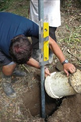
  1. Pour concrete into the formed hole. Use a level to make sure the post stays straight during construction.
  2. Tamp down concrete while pouring the form. See working with concrete section of the website
1_htm_m4fc78499

  1. Earth is mounded around the post.
  2. Sticks are placed on the elevated mound so that a cover can be placed over the whole post structure during curing.
1_htm_m5919de02

  1. Use a level to make sure the post is level in the concrete.
  2. Cover the concrete during curing. See working with concrete section at the end of this manual.
Using Trees to Elevate Tubes
1_htm_m4affdb7b Note: There are several ways of attaching to trees. The method shown in the following photos shows hardware clips. Volunteers have encountered problems with these clips cutting the plastic sheathing on cables when put under tension. If this is the case, in lieu of clips, the cable can be tied in a knot around the tree by making a loop and running around the tree and back through the loop.

1_htm_3ed7a4e9

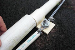
  1. Loop cable around the tree and slide on hardware clip.
  2. Tighten nuts extremely well using pliers.
1_htm_2407eb4b
  1. Leave about 12” of cable from the hardware clip around the tree to the end of the cable.
  2. Run cable through turnbuckle hardware.
  3. Create loop at end of cable by doubling back. The eye of the turnbuckle should be in this loop.
  4. Tighten loop with hardware clip.
1_htm_29c428fa
  1. Loosen bolts on turnbuckle as shown in the picture.
  2. Create loop in new piece of cable using hardware clip.
  3. Attach new cable to hook on turnbuckle hardware.
  1. Repeat above attachment method on other side of bridge if attaching to another tree. For smaller crossings (< 20 feet), one turnbuckle should be sufficient. For larger crossings, the extra turnbuckle will help add more tension in the cable.
  2. For crossings with two turnbuckles, measure out distance of cable to connect to other side of bridge. Pull on cable to add tension before deciding where to cut the cable.
1_htm_m61289ab8

  1. Paint any tubes that will be exposed to UV rays.
1_htm_m63628680
  1. Attach tube to cable using nylon string or wire. This solution could use some work. Nylon string tends to degrade in the sun. Wire will rust. If you're able to find plastic coated metal or can make thin PVC rings from a larger diameter PVC tube, this is the preferred choice for attachment.
  2. Make sure attachments are located about every three feet and are have some slack since the cable will move when put under tension.
1_htm_3a257af3

  1. Elevate cable and tube.
  2. Attach cable as needed using hooks of turnbuckle hardware.
  3. Tighten bolts in turnbuckle hardware as needed. The tube should be straight with very little sag in the middle of the crossing.
Using Rocks to Anchor
1_htm_m6935933c
To the left is a picture of a potential rock anchor. This was taken from an existing system, so there are no installation instructions at this time.

Other Considerations
1_htm_53e05902

If your bridge crossing involves a transition from the ground to being elevated, sheath the transition point in about 4' of larger tubing. This will help protect the inner tube from machetes or animals that may come in contact with where the tube enters the ground.
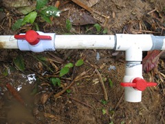
1_htm_m6e89adab Since you'll be shutting off the water for bridge maintenance or construction, the bridge may also be a location to install a shutoff valve and/or cleanout valve as shown in the picture to the left.

Monday, August 22, 2011

Installing Principle Valve Boxes

Construction
1_htm_m74d6e432

  1. Fill area below the valve box and inside the valve box with gravel. This will help with drainage and future maintenance of the valve.
1_htm_m675fab97

  1. Place the lid on the valve box and backfill the work area. The area should be backfilled with dirt only. Rocks should be removed.
1_htm_1a9a997a
  1. This is the finished valve box. The lid is bolted to the box to deter vandalism.